Nesse vídeos mostramos uma configuração simples de um Switch ArubaOS-CX para gerenciamento de switches com funcionalidades como: VRF, NTP, Syslog, SNMP, SSH, usuários local, RADIUS, TACACS entre outros.
Aruba
Switches ArubaOs – Configurando um Range de Interfaces
Os switches ArubaOS permitem o agrupamento de portas para determinadas configurações, como por exemplo, atribuir uma VLAN a diversas portas ao mesmo tempo.
Segue abaixo uma dica que pode agilizar a vida de muitos administradores:
switch# configure terminal
switch(config)# interface 9-10
! agrupando  as portas 9 e 10 para configuração
switch(eth-9-10)# untagged 2
! configurando as portas para participarem da VLAN 2
switch(eth-9-10)# dldp enable
! habilitando o dldp nas portas 9 e 10
switch(eth-9-10)# exit
switch(config)#
switch(config)# interface 11-15,17
! agrupando  as portas 11, 12, 13, 14,15 e 17 para configuração
switch(eth-11-15,17)# untagged vlan 5
! configurando as portas para participarem da VLAN 5
Validando a configuração com o comando show running-config structured :
switch(config)# show running-config structured | begin interface 9
 interface 9
    dldp enable
    untagged vlan 2
    exit
 interface 10
    dldp enable
    untagged vlan 2
    exit
 interface 11
    untagged vlan 5
    exit
 interface 12
    untagged vlan 5
    exit
 interface 13
    untagged vlan 5
    exit
 interface 14
    untagged vlan 5
    exit
 interface 15
    untagged vlan 5
    exit
 interface 16
    untagged vlan 1
    exit
 interface 17
    untagged vlan 5
    exit
Até logo!
Switches ArubaOS – Configurando OSPF com autenticação MD5
O protocolo OSPF suporta a Autenticação para estabelecimento de adjacência com vizinhos. O Processo incrementa segurança ao Roteamento Dinâmico com troca de chaves em MD5.
Para ativarmos a Autenticação é necessário informar qual a Área OSPF utilizará a Autenticação e precisaremos habilitar a chave na Interface que formará a adjacência.

Configurando
Segue abaixo a configuração dos Switches.
SwitchA
ip routing
key-chain "ospf_aruba"
key-chain "ospf_aruba" key 1 key-string "it_net"
router ospf
   area backbone
   redistribute connected
   redistribute static
   enable
   exit
vlan 32
   ip address 10.168.32.133 255.255.255.252
   ip ospf 10.168.32.133 area backbone
   ip ospf 10.168.32.133 md5-auth-key-chain "ospf_aruba"
   exit
vlan 10
   ip address 10.10.10.1 255.255.255.0
   ip ospf 10.10.10.1 area 10
SwitchB
ip routing
key-chain "ospf_aruba"
key-chain "ospf_aruba" key 1 key-string "it_net"
router ospf
   area backbone
   redistribute connected
   redistribute static
   enable
   exit
vlan 32
   ip address 10.168.32.134 255.255.255.252
   ip ospf 10.168.32.134 area backbone
   ip ospf 10.168.32.134 md5-auth-key-chain "ospf_aruba"
   exit
Verificando o estabelecimento de vizinhança
SwitchA# sh ip ospf neighbor

 OSPF Neighbor Information

                                                         Rxmt         Helper
  Router ID       Pri IP Address      NbIfState State    QLen  Events Status
  --------------- --- --------------- --------- -------- ----- ------ ------
  10.168.32.133   1   10.168.32.134   DR        FULL     0     7      None
Até logo.
Vídeo: Switches ArubaOS – Configurando o Terminal Monitor
Para configurar o terminal monitor nos Switches ArubaOS utilize os comandos abaixo na CLI:
debug destination session
debug event
Para desabilitar utilize o comando “no debug all”
Vídeo: Switches ArubaOS-CX – Configurando Roteamento entre VLAN no EVE-NG
Nesse vídeo, montamos um laboratório no EVE-NG com Switches ArubaOS-CX demonstrando a configuração do roteamento entre VLANs.
Switches ArubaOS – Comandos úteis para inventário
É recomendado que a equipe responsável pela administração dos switches ArubaOS mantenha um inventário atualizado dos ativos, os comandos abaixo podem auxiliar no levantamento para essas informações:
Hostname:
Switchl# show running-configuration  | hostname
hostname "Switch1"
Endereço IP:
Switch1# show ip

 Internet (IP) Service

  IP Routing : Enabled


  Default TTL     : 64
  Arp Age         : 20
  Domain Suffix   :
  DNS server      :

                       |                                            Proxy ARP
  VLAN                 | IP Config  IP Address      Subnet Mask     Std  Local
  -------------------- + ---------- --------------- --------------- ----------
  default              | DHCP/Bootp
  GERENCIAMENTO        | Disabled
  vlan31               | Disabled
  vlan32               | Manual     10.1.2.134   255.255.255.0    No    No
  VLAN34               | Disabled
  VLAN100              | Disabled
  VLAN101              | Disabled
  VLAN102              | Disabled
  VoiceVLAN            | Disabled


                               Loopback Interface

  Loopback     | IP Config    IP Address      Subnet Mask
  ------------ + ------------ --------------- ---------------
  lo7          | Manual       10.1.7.7         255.255.255.255
Versão do SO:
Switch1# show version
Image stamp:
 /ws/swbuildm/rel_portland_qaoff/code/build/btm(swbuildm_rel_portland_qaoff_rel_
portland)
                Aug 24 2015 12:38:43
                K.15.17.0008
                599
Boot Image:     Primary

Boot ROM Version:    K.15.30
Modelo de Hardware:
Switch1# show modules

 Status and Counters - Module Information

  Chassis: 5406zl J8697A!        Serial Number:   SG048SU123
                              Allow V1 Modules:   Yes

  Management Module: J8726A      Serial Number:  ID044AS0RT   Core Dump: YES

                                                                      Core  Mod
  Slot Module Description                     Serial Number  Status   Dump  Ver
  ---- -------------------------------------- -------------- -------- ----- ---
  A    HP J8702A 24p Gig-T zl Module          SG047ATAAA     Up       NO    1
Transceiver:
Switch1# show tech transceivers

Transceiver Technical Information:

 Port # | Type   | Prod # | Serial #   | Part #
--------+-----------+------------+------------------+----------
A21     | 1000SX | J4858C | 3CA404JCA | 1990-3662
Localização física (Site e Rack), configurados previamente na config SNMP:
Switch1# show  system
 Status and Counters - General System Information
  System Name        : HP-5406zl
  System Contact     : IT TEAM
  System Location    : IT OPS Network - Saquarema - RACK A1
Aruba Central – Descobrindo qual a versão do Central
Para validar qual a versão do Aruba Central está sendo executada, efetue o seguinte procedimento:
Uma vez autenticado e com acesso ao dashboard, digite /admin/version como complemento da URL
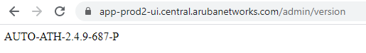
Identificar a versão é ideal para validação de funcionalidades, manuais e na geração documentos técnicos.
Switches ArubaOS-CX: Client IP Track
Quando a funcionalidade Client Track IP está habilitada, o switch monitora o tráfego de rede para identificar o endereço IP de cada dispositivo conectado à rede. Ele então usa essa informação para criar uma tabela de rastreamento de clientes, que mostra o endereço IP de cada dispositivo, juntamente com o número da porta do switch à qual ele está conectado.
Isso permite que os administradores de rede identifiquem rapidamente a localização física de cada dispositivo, o que pode ser útil para solução de problemas e para fins de segurança. Por exemplo, se um dispositivo estiver causando problemas de rede, o administrador pode usar a tabela de rastreamento de clientes para identificar rapidamente o switch e a porta à qual o dispositivo está conectado.
A funcionalidade Client Track IP também pode ser usada em conjunto com outras ferramentas de gerenciamento de rede, como o Aruba ClearPass Policy Manager, para fornecer uma visão mais completa da rede e dos dispositivos conectados a ela. Em geral, a funcionalidade Client Track IP ajuda os administradores de rede a gerenciar e solucionar problemas em redes complexas de forma mais eficiente.
**Configuração do Client Track IP**
client track ip
*! configurações para descoberta do IP dos dispositivos cliente e envio do framed-ipaddress no accouting da autenticação 802.1x (atributo 8)*
vlan 10
client track ip
vlan 20
client track ip
*! Habilitando na VLAN*
interface 1/1/24
no shutdown
description UPLINK
no routing
vlan trunk native 1
vlan trunk allowed 10, 20
client track ip disable
*! filtrando o client track ip na interface de uplink*
Switch# **show client ip**
MAC Address Interface VLAN IP Address
aa:56:27:f2:c1:aa 1/1/3 10 192.168.10.136
f4:bb:7f:c7:37:8c 1/1/21 20 192.168.20.147
f4:bb:7f:c7:30:ff 1/1/22 20 192.168.20.141
Switches ArubaOS-CX: Cisco Rapid Per-VLAN Spanning-Tree (RPVST)
O Per VLAN Spanning Tree Protocol (PVST) é uma versão do protocolo Spanning Tree Protocol (STP) que permite que múltiplas instâncias de STP sejam executadas em uma rede local, garantindo que cada VLAN tenha sua própria topologia de spanning tree.
Quando o PVST é ativado em uma VLAN, cada switch na rede mantém uma instância do STP para cada VLAN, em vez de uma única instância do STP para toda a rede. Cada instância de STP cria uma topologia de spanning tree separada para sua VLAN correspondente.
Os Switches Aruba CX permitem a configuração do Rapid PerVLAN Spanning-Tree para interoperabilidade com Switches Cisco, por exemplo.
Para efetuar a configuração basta mudar a versão do STP para o RPVST, configurar globalmente as VLANs que terão suas instancias como PerVLAN e alterar a prioridade, se necessário.
spanning-tree mode rpvst
spanning-tree
spanning-tree vlan 35,36,65,66
spanning-tree vlan 35 priority 15
spanning-tree vlan 36 priority 15
spanning-tree vlan 65 priority 15
spanning-tree vlan 66 priority 15
6300# **show spanning-tree summary root**
STP status : Enabled
Protocol : RPVST
System ID : b8:d4:e7:a0:67:00
Root bridge for VLANs :
VLAN Priority Root ID cost Time Age Dly Root Port
—
VLAN35 4096 00:23:04:ee:be:c8 2004 2 20 15 lag1
VLAN36 4096 00:23:04:ee:be:c8 2004 2 20 15 lag1
VLAN65 4096 00:23:04:ee:be:c8 2004 2 20 15 lag1
VLAN66 4096 00:23:04:ee:be:c8 2004 2 20 15 lag1
Aruba Central – AIOps – Insights REAIS !
Nesse vídeo mostramos o uso do Aruba Central com AIOps com a coleta de alguns insights em um cenário em produção.
